

For this project, I was responsible for designing and meticulously planning the entire system from the ground up. I handled system design, software development, cost optimization, electrical engineering, and hardware calibration, as well as creating wiring schematic diagrams. To automate the blast gates and dust collector, I developed custom software code in C++, including UI and system interaction. More info with source code on GitHub.

Dust Fairy
Dust Fairy is an Arduino based Dust Collection system automation with automatic blast gates coordination and auto on/off control.
Abstract
This project presents a multifunctional system design, named Dust Fairy, for achieving smart and compact dust collection system automation with multiple workstations in a shop, using readily available inexpensive components such as commonly found sensors, relays, and contactors. The system is designed to accommodate any size setup, from small home-hobbyist garage setups to large industrial systems, without breaking the bank. The proposed design utilizes pneumatic pistons for opening and closing pneumatic blast gates and turning on and off dust collection systems, and custom software code in C++ to independently automate the system based on sensor input.
Introduction
Industrial systems of larger sizes are incredibly costly and complicated, while small shop systems are expensive, very limiting in customization, and not reliable in the long term. The use of an Arduino-based system can help in centralizing and infinitely customizing the project with inexpensive readily available components, such as commonly found sensors, relays, and contactors. This project aims to provide a solution for anyone who wishes to have smart and compact dust collection system automation with multiple workstations in a shop without breaking the bank and with virtually infinite customization with the code and the option of future expansion.
Idea
The proposed Dust Fairy system is a DIY, inexpensive, and multifunctional system designed to control relays and solenoids to open and close pneumatic blast gates and turn on and off dust collection systems via a contactor. The system is housed neatly in one spot for easy access and troubleshooting. Pneumatic pistons are utilized in the design due to their high reliability, adjustability in speed of motion with pressure-limiting attachments, powerfulness, and ease of mounting. Compared to servo motors, pneumatic pistons have more advantages in this application. The system is designed to accommodate any size setup, and its original design included split core current transformers by YHDC SCT013, which can be added to the system if needed. The custom software code in C++ independently automates the system based on sensor input.
SCHEMATIC DIAGRAMS
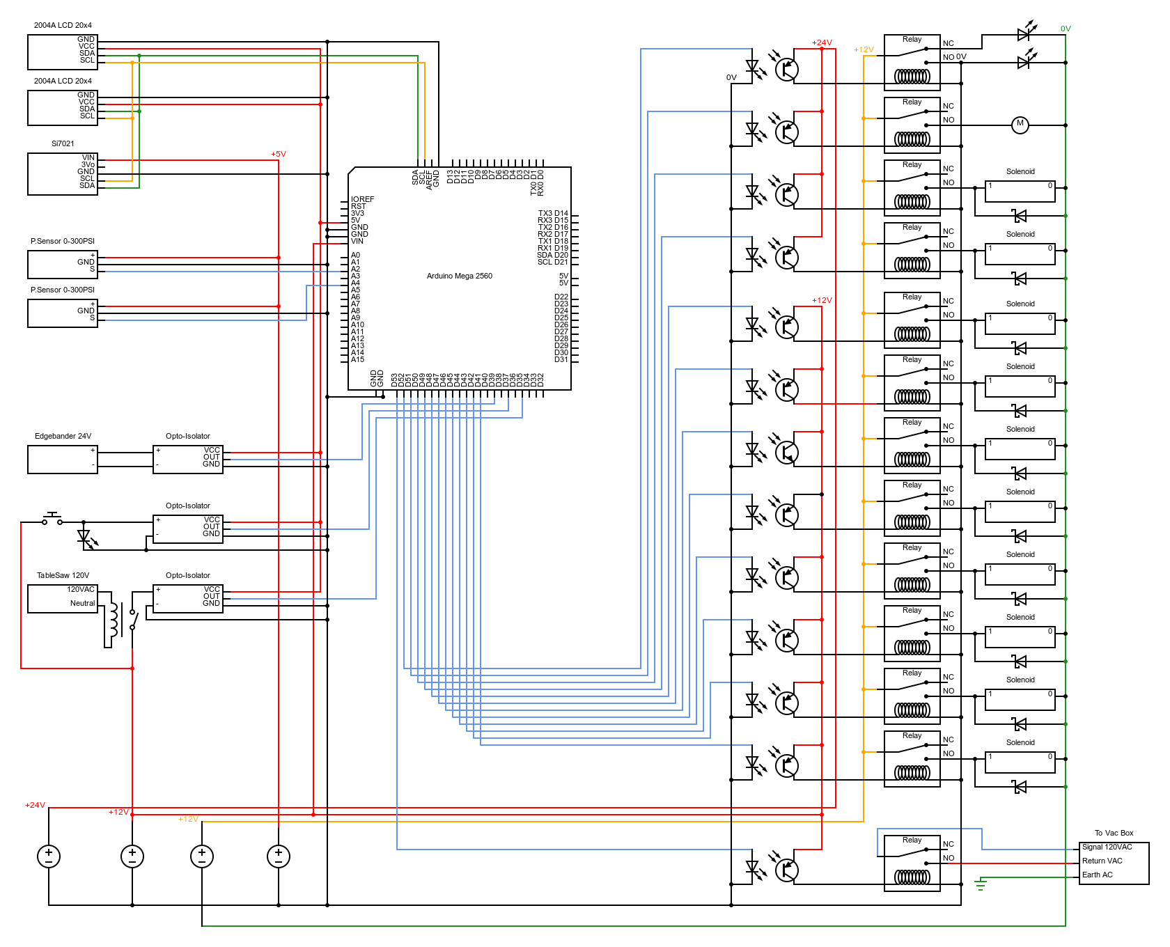
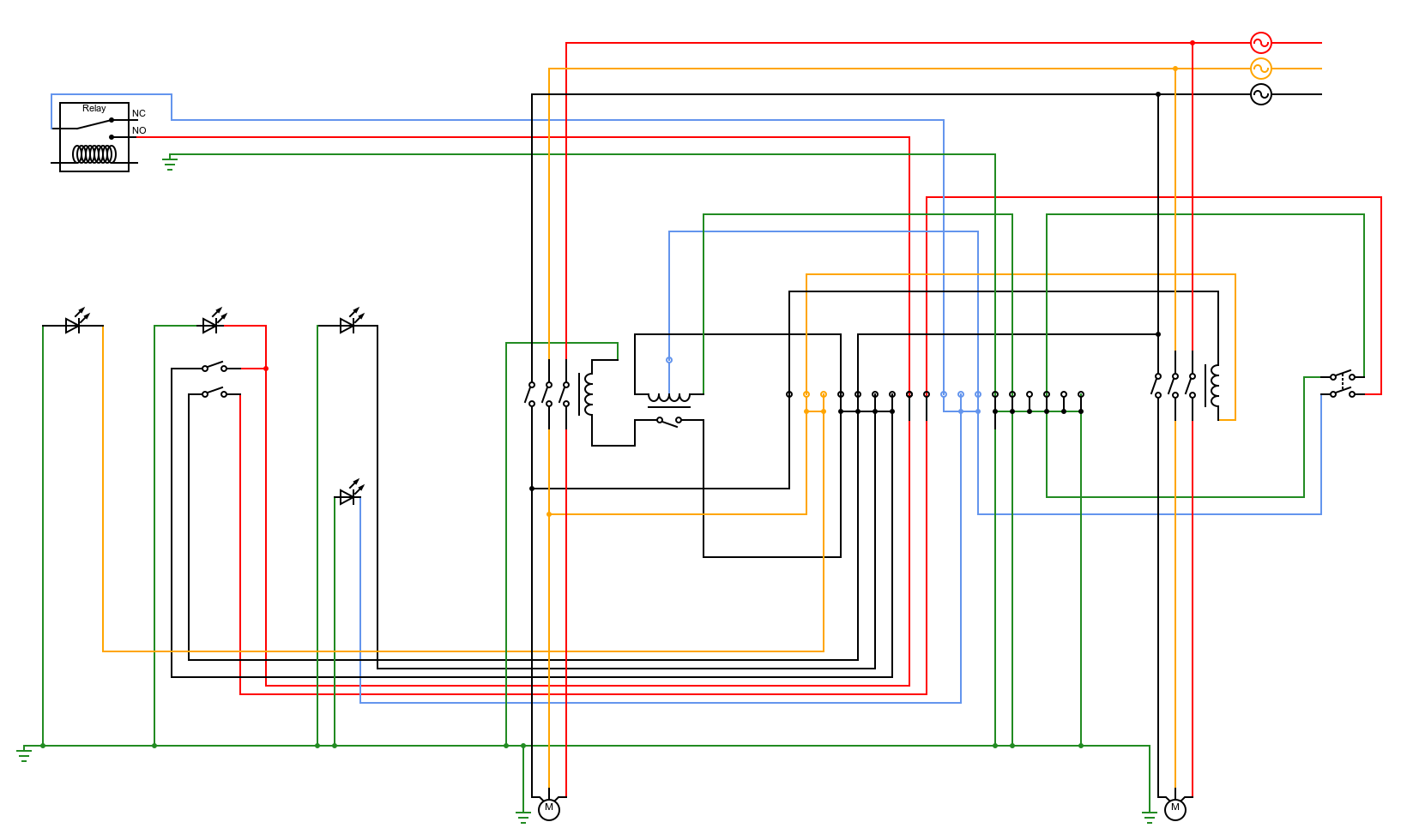
How it works
The Arduino MEGA controls the system, including the gates and main contactor via relays. It collects information from sensors measuring pressure, temperature, and humidity, as well as high and low signals from OPTO-ISOLATORS connected to buttons and solenoids. The system also regulates air solenoids, 120v contactors, LED lights, and a 12v cooling fan for the electronics housing via a set of OPTO-ISOLATED relays.
The blast gates are air-controlled, and solenoids control the opening and closing of the gates via a pneumatic piston connected to a compressed air system.
The system has several safety measures including a ten-second off delay of the dust collection system with all gates open, always open gates once off, a designated safety gate that triggers open when the manual button is activated without other equipment running, and the system will not close any gates that are used if the manual button is pressed while equipment is running. Additionally, a high air pressure sensor is built in to monitor and display a warning message if the air pressure drops below a programmed value.
UI
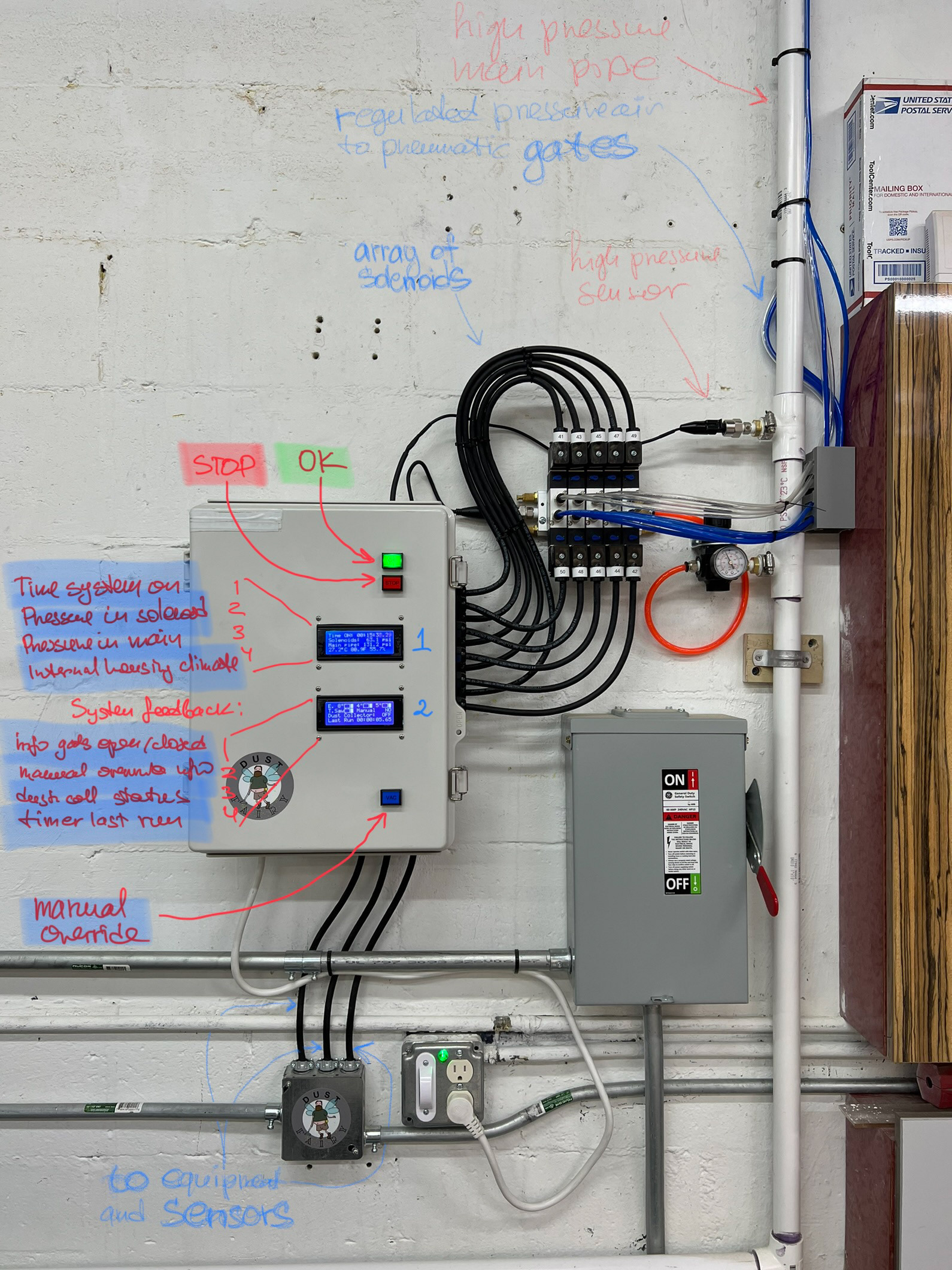
The system includes two LCD displays, each with four lines.
LCD 1 shows the total system uptime, the pressure in PSI of the solenoid manifold, the pressure of the main system displayed in PSI, and the temperature in Fahrenheit and Celsius, along with the humidity of the main hardware housing box.
LCD 2 displays the current status of the blast gates using custom-designed infographics that resemble blast gates and save space. It also displays the status of the dust collector, the counter of the last runtime of the dust collector, and whether the manual override is triggered.
The housing is equipped with green (OK) and red (STOP) lights to indicate whether the system requires attention or is ready to operate. Additionally, there is a blue (VAC) button for manual override that turns on the system until the button is pressed again.
Boot up and self check process
Turn MAGIC on!
Turning on equipment, closed blast gates 8, 4 and 5 and turned on dust collector